Workshop catchup: Bass edition
Published 3 Jan 2025
Tags: bass, CAD, laser-cutting
In the previous update I talked about the process of designing my first bass guitar, my Delfinen Bass, looking at how it differs from a regular electric guitar design. This set of notes will catch us up on how the build of that has got going.
Refinement
Before we start in the workshop side of things, a quick update on the CAD model, as it’s had a couple of tweaks since I started it. On the front:
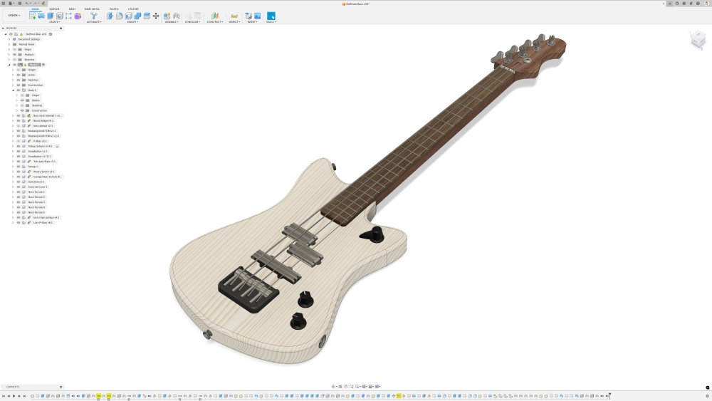
Visually it’s had a change as the roasted maple wood, which you’ll see below, is quite dark, so I felt I wanted to work that in. Pickup wise I’ve always wanted to try out the Lace Aluma style pickups ever since I saw Philip McKnight demo their P90s on his youtube channel. The pickups have an unusual design which don’t use any copper windings but are still passive pickups, which I find intriguing, so I plan on giving them a go on this build. I feel this style of pickup would work quite well on an Älgen style guitar, and so this is just an excuse to try them out here.
More importantly, before I could hit the workshop I needed to fill in a bunch of details on the neck and body designs that impact the actual early build stages, which starts with some bits visible on the back of the guitar:
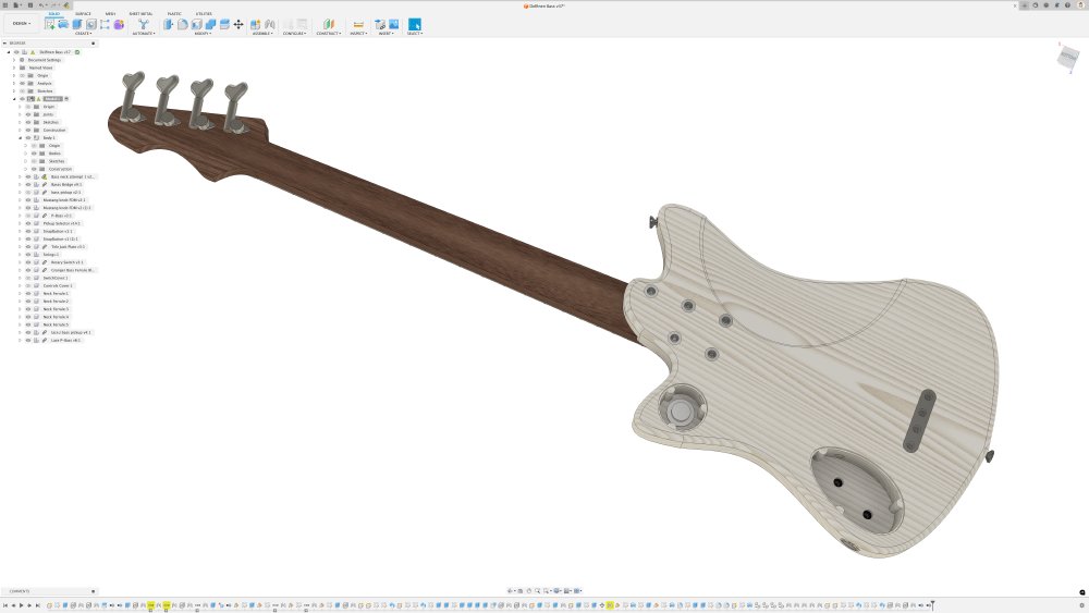
Here I added non-visual but technically important bits like the mounting posts for the screws in the cavities; not exciting, but I need these all in place before I can make the templates for cutting the wood. Similarly I added the cavities in the neck for the graphite rods that will go in the neck alongside the truss-rod to deal with the extra strain on a bass from it’s chonky strings. You can see these here with the fretboard hidden:
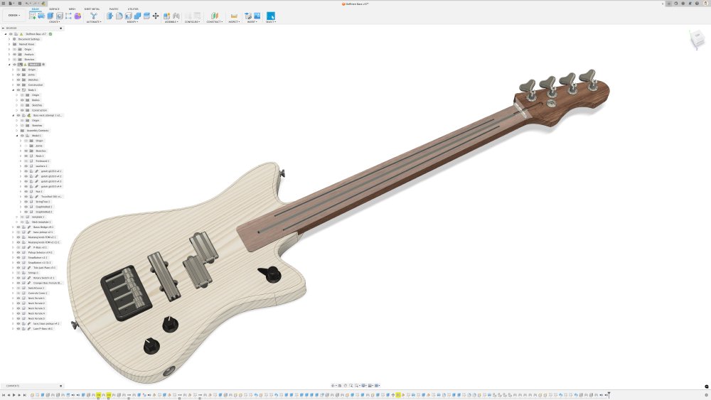
At this stage it’s not just a matter of drawing them into the CAD model, I do need to know how I plan to make these cavities: what tools will I use, will I need any new bits for the router, what will be my reference points for any cuts, and so forth. You can draw anything you like in CAD, but that doesn’t account for you being able to actually make it, so as I’m filling in these details I need to also work out how I plan to build it.
What you can’t see is that I also had to do a bunch of fiddling with my CAD in Fusion just to get my design into the right state for me to build templates from my model. Fusion 360, the CAD tool I use, is based on the concept of a timeline, which is all those icons you can see at the bottom of the screenshots I’ve posted; that’s the history of all the operations I made to build the design. The order in which you do these can have important consequences, and I often come slightly undone as when building a design I often add early on visual references for myself so I can get a sense of how the instrument will look, even if they’re not technically needed in the CAD model. By adding those early I tend to pollute the timeline with things that get in the way later.
For instance, the rounding over of the body edges, which I’ll do by hand using a palm-router with a round-over bit, isn’t technically needed in the CAD, but it helps me see what the finished guitar will look like. But by adding that feature in CAD, if I want to say make a 2D-template based on the front of the guitar, Fusion will account the rounded over bit, and so my template will be too small being based just on the actual flat surface in the CAD model. If I added all the visual bits and the end I could just disable the last few bits of the timeline and all would be good, but because I do them before say I add the cavities for the pickups, I can’t readily do that. So I spent an hour or two having to unpick my design to “fix” all this.
I shouldn’t know better than this by now, but that needing visual cues as I go along is super important to my design process, so I end up having to do all this tidying at the end.
Materials
Whilst I was doing this second round of design work, I had already secured the materials for this build. My plan was to make the body with poplar, due to its light weight, and the neck out of roasted-maple, again as maple is strong and roasted-maple is lighter weight due to having less moisture in it. Fortuitously for me, my workshop-mate Matt had a spare poplar body blank he’d prepped but in the end didn’t use, which he was happy to trade me:
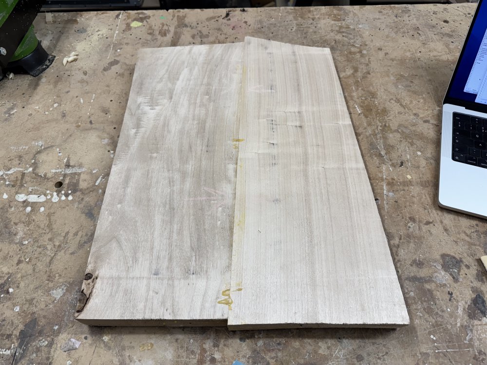
He’d even done most of the prep, which was great news. Truth be told, workshop time has been scarce of late, and so I’d decided that in order to speed this build up I’d just pay extra for a one-piece body rather than the usual jointed two-piece body approach I use (which is more affordable). Thankfully Matt’s offer of materal also meant I skipped the jointing stage, so I was delighted at this bit of good fortune.
For the neck, I ordered the wood, but wanting roasted-maple I had to switch from my usual wood supplier, Exotic Hardwoods UK, over to another supplier of instrument woods, David Dyke Luthiers’ Supplies. After putting in my order, a few days later a nice parcel of wood arrived:
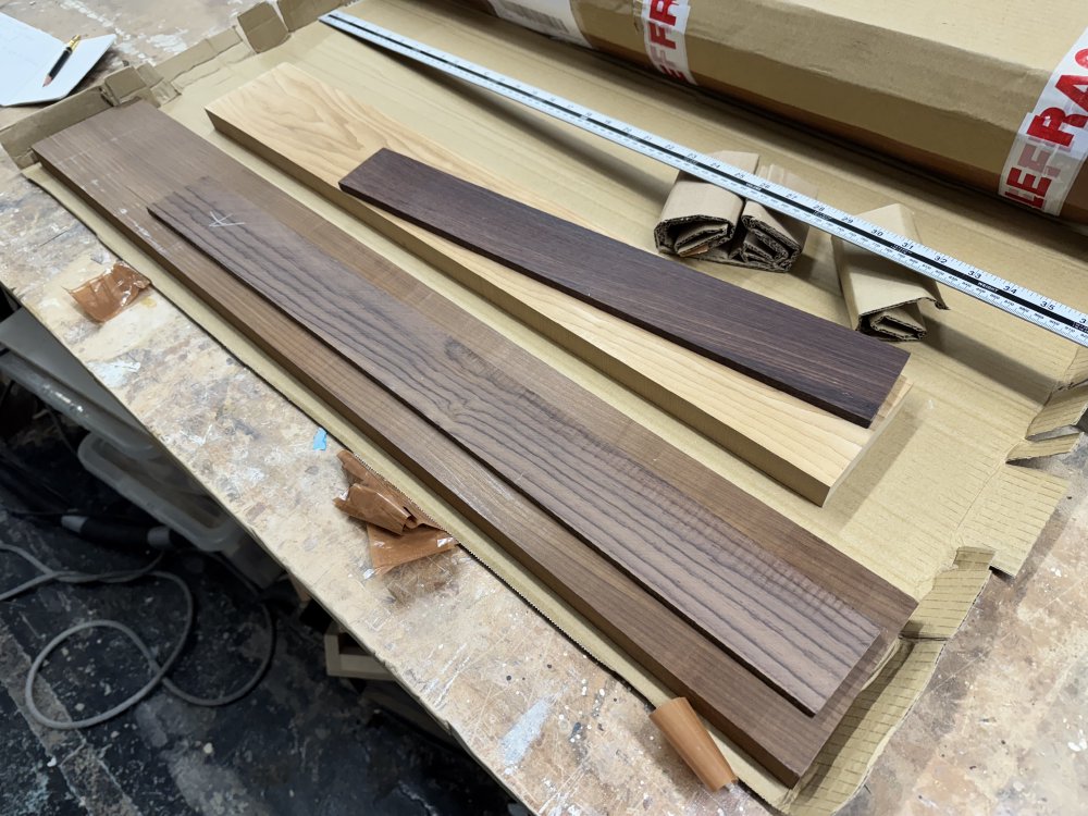
The wood on the left is the neck and fretboard for the bass, and the wood on the right is for a regular guitar neck. Interestingly both necks are roasted-maple, but clearly one has reacted quite differently to the roasting process.
With that, I have all the wood ready to make a bass. You can hopefully see the resemblance between the material and its final form:
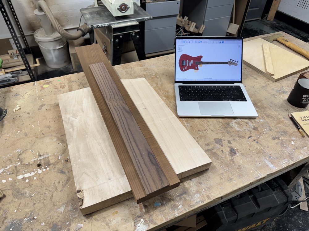
Template time
I was tempted to try doing some of this build on the CNC-router to speed things up a bit, after Matt offered to let me use his, but given I knew I’d end up doing a bunch of the work on the bass over the xmas period when he was unlikely to be around, I opted to just go with my usual approach of making laser-cut templates, and then using a combination of band-saw and palm-router to get the wood into the right shape.
One catch with this for the bass is that the neck is big enough that I can’t use a regular 600x400 mm sheet of acrylic for making the templates as I do for the regular electric-guitar necks, I had to step up to a 1000x600 mm sheet, the next size up, which is notably more expensive that simple math would lead you to assume. I’m also glad that the local maker space got a slightly larger laser-cutter a couple of years ago, as this sheet wouldn’t fit in the older one!
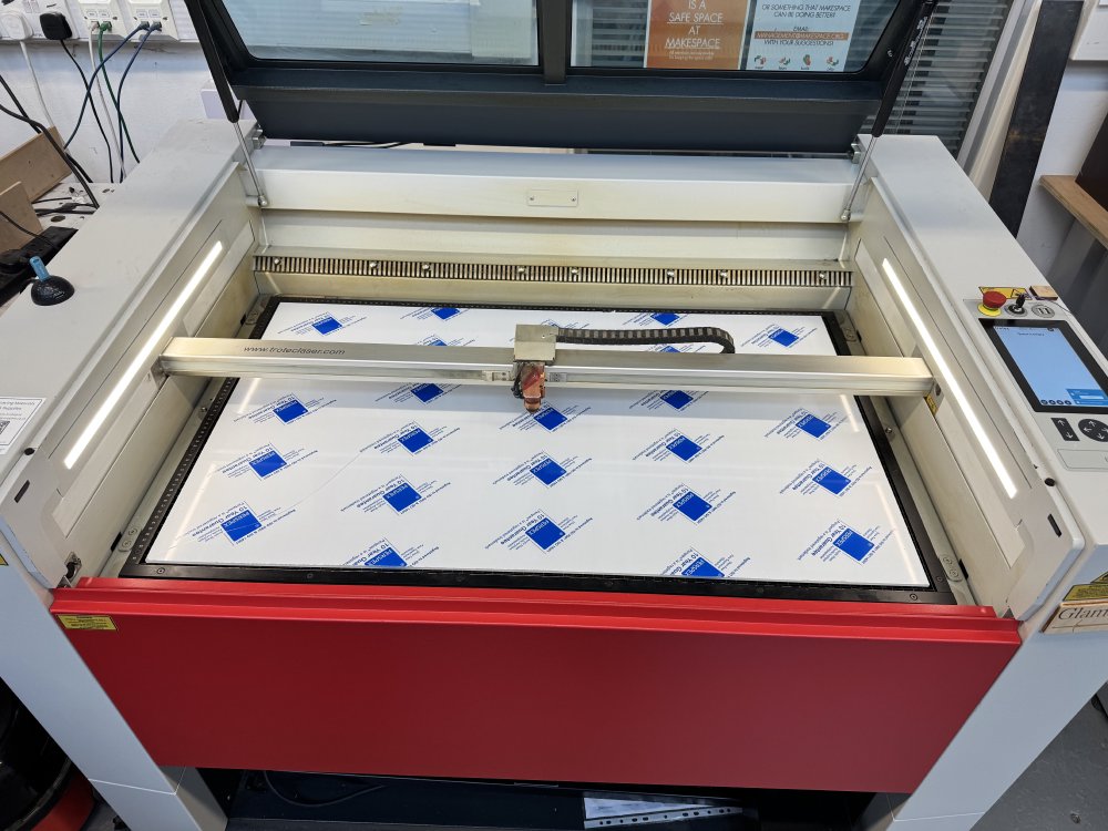
Unfortunately cutting all this didn’t go as smoothly as I’d have hoped, as the laser-cutter seemed to be having power issues. Often laser-cutters tend to lose power if they’ve been heavily used and the lenses/mirrors have got dirty from smoke and not been cleared, but in this instance there was something more odd going on: the power seemed to fade over the duration of the cut. You can see it in the picture here, where the start of the cut is more clearly made than the end (it’s going in a counter clock-wise direction).
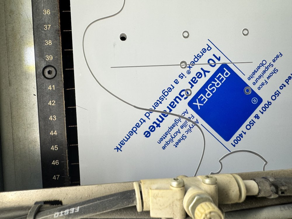
This lead to the first attempt to cut a neck-template not working, as it’d not properly cut through the material at the start/stop point, despite me going over it a second time after I spotted the issue, and it made the top of the template ragged:
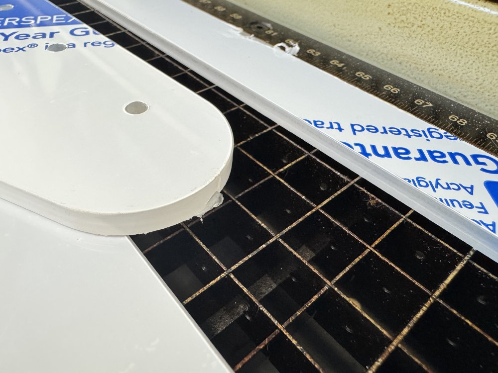
Whilst I could try sanding that smooth, I’ve learned many times over that any marks in the template show up in the wood and are then a pain to sand out, so I opted just to re-cut this one. But what should have been a fairly straight forward job at the laser-cutter for an hour turned into a half day of prodding and fighting with it.
I often get asked why I don’t do more of my guitar building with CNC things, and whilst partly it’s because I enjoy the manual process, it’s also partly down to nonsense like this. If I made more guitars and had my own dedicated machines that I used regularly, then whilst they’d still have issues occasionally, in general using the machines would be more of a known quantity. But using shared machines like this I just can’t predict how they’re going to behave, and so I prefer to replace that risk with slower but more predictable manual processes. One day I’d like to go back to CNC-routing for some things, but not whilst I do so few instruments each year.
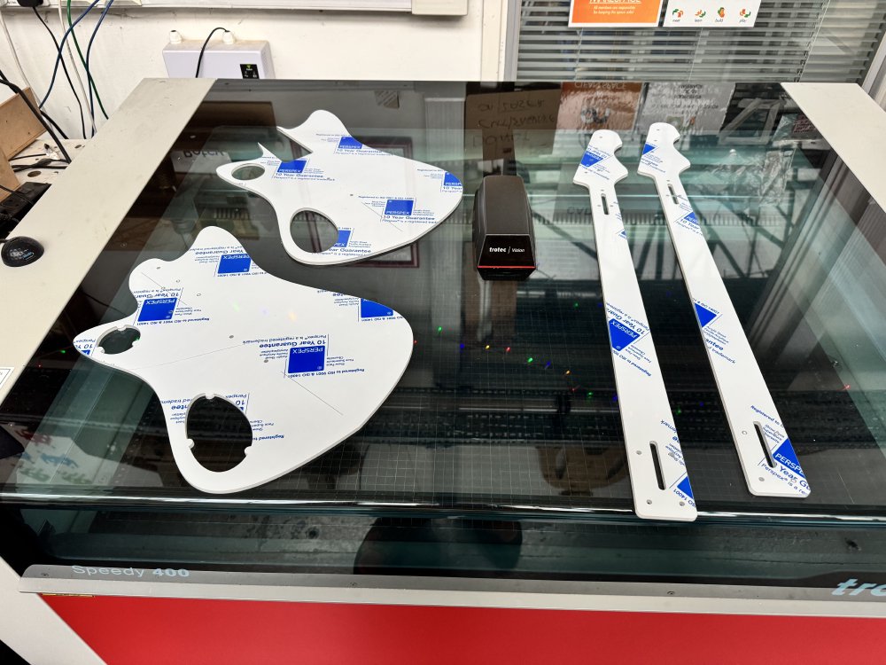
Anyway, machine frustrations aside, I eventually turned one large sheet of acrylic into the templates I need to shape my bass guitar.
This also means for the first time I get a sense of how the guitar is at life size:
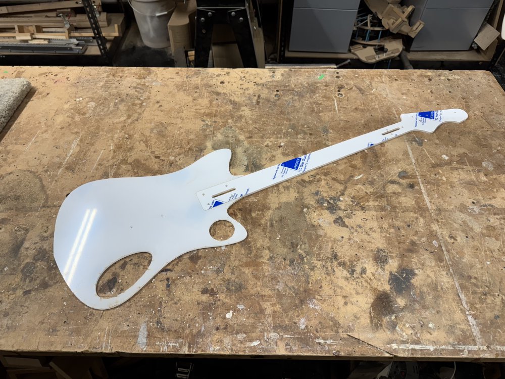
Quite pleased with how it feels at full size. It’s not always the case that what looks good on screen will look good in real life, so it’s a nice sanity check at this point before I start making hard-to-undo changes to my raw material.
The acrylic is actually clear, rather than white, that’s just the protective film that is removed before use. I use clear so that I can see the wood grain under the sheet and check that it I’m happy with the bit of the wood I’m using. I also etch on a centre line on the template that I can then line up with the join line on the wood.
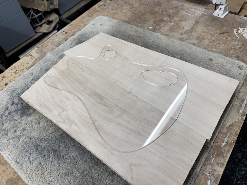
Before I can use the templates there’s one final thing I need to do, which is countersink the mounting holes for the screws, so they don’t interfere with the router. Alas, the laser cutter I have doesn’t have a magic multi axis head, so I do this on the pillar drill.
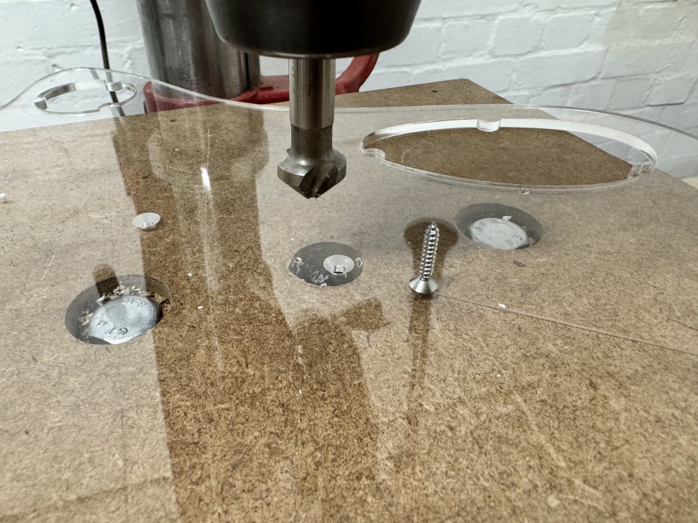
With that done, it’s finally time to get started!
First cuts
Before I can cut the profile with the template, I first need to ensure the body blank is perfectly level and at the right thickness. Although in theory the joint faces should be at 90˚ to the front/back they faces won’t be perfectly so in general (particularly if you used a hand-plane to get the joint faces flat), and so the body will have a slight V shape to it most likely, which isn’t great for attaching templates.
The first step was to remove the excess glue along the seam:
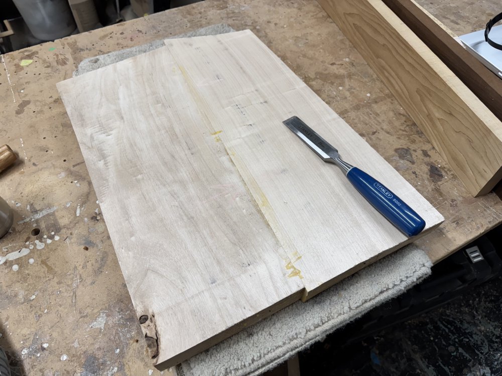
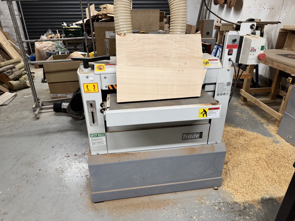
With that tidied it was over to the thicknesser to get it properly flat and down to the thickness I wanted. Matt had already thinknessed the two halves before he jointed them, so I didn’t need to do too much here: the pile of wood to the side you see here is from another workshop-mate working on the table router, not from my thicknessing!
Now with the body prepped, I can finally attach the template, taking care to line up the centre line and check on both sides that I’m going to avoid any features in the wood that I don’t want. In this case there’s a knot on the back towards the bottom edge, which is why I mounted the template quite near the top edge. For those curious about using screws to mount the template, the screw holes are all in areas where later on the wood will be removed: the top one is in the neck pocket at the lower two are where the pickups will go, so no evidence will remain of these screw holes by the time the body is finished.
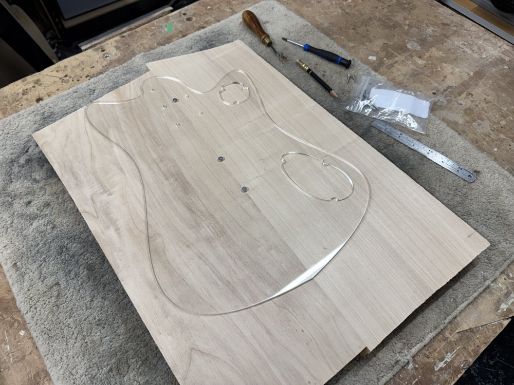
With the template on, the next step is to remove the bulk of the wood using the band-saw. Normally for bulk material removal I’d use a chunky blade eat through the material, but because of the curves on the body, and because poplar is relatively soft, I opted instead to switch out the blade for a smaller one that is better for following curves. Changing a bandsaw blade is a relatively quick process on the Record bandsaw I have, and so it’s something I’m happy to do for each bit I work on if necessary.
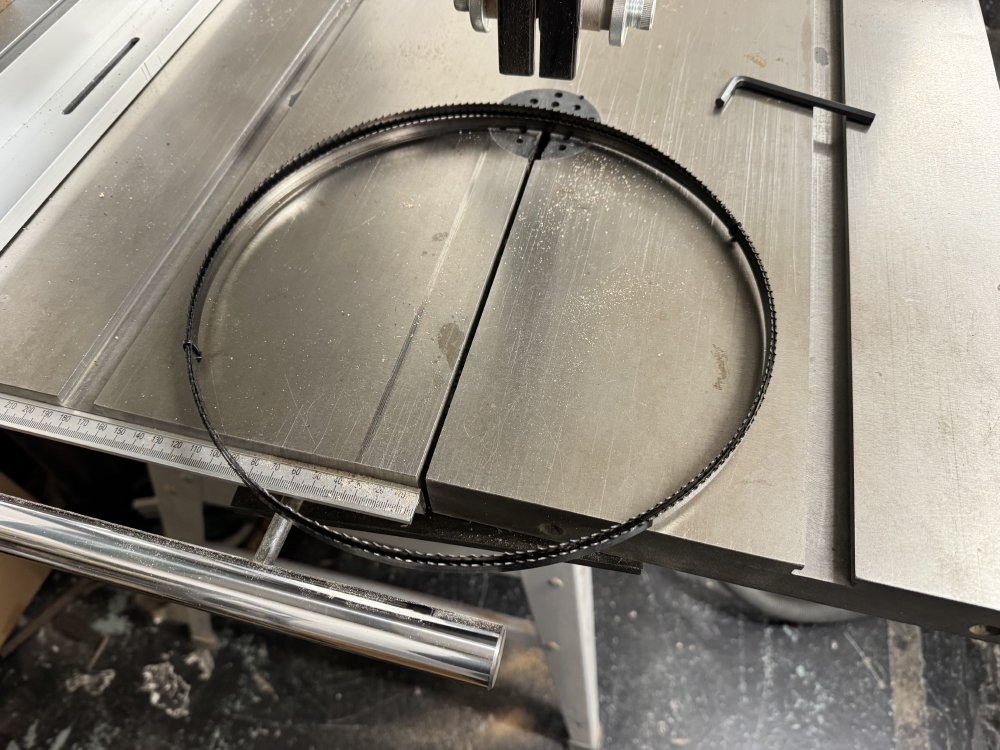
A few minutes later and I had my body roughed out:
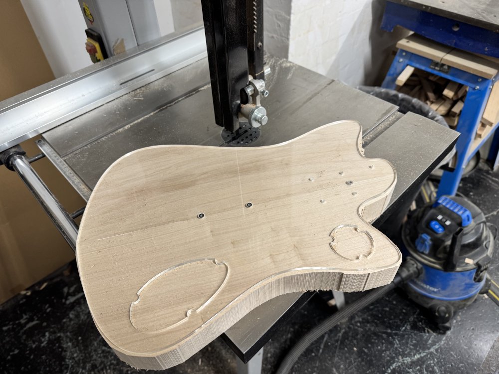
You can see that the cut isn’t the best - given I just put on a fresh blade and thought I’d set up the guides right I’d have expected a smoother cut, so I’m not sure what I did wrong there - I set the tension appropriately and adjusted the guides, but clearly the results are not great. Thankfully I’m just roughing at this stage, but that definitely isn’t acceptable for other jobs I used the bandsaw for. After doing this I returned the bandsaw to having a heavier blade on it, as my workshop-mates mostly use it for rough cutting, and that was cutting cleanly.
Mystery aside, the band-saw stage is just to get the bulk of the material off, but not to get the actual body down to size. For that I use a palm-router with a pair of follow-bits that have a guide bearing to follow the outline of the acrylic template exactly. Routing though should generally be seen as a tool for removing just a small amount of material, hence the band-saw stage first.
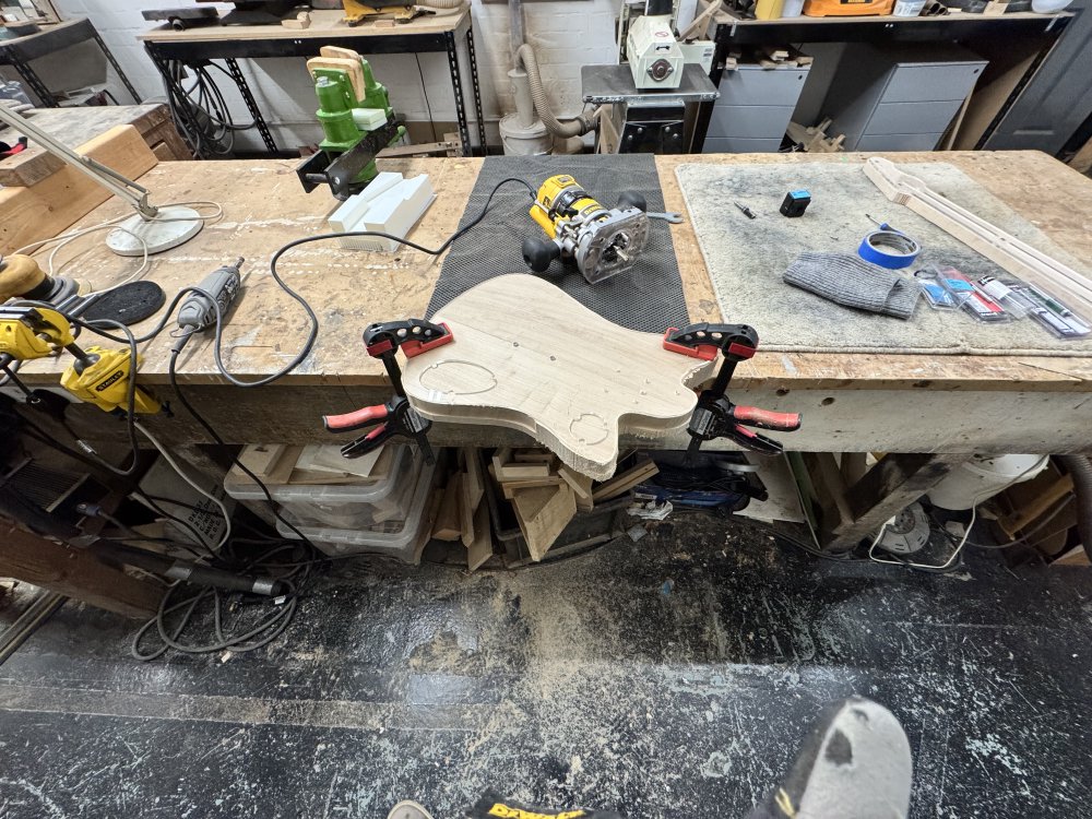
This is where I make a big mess similar to the pile next to the thicknesser, only I’m doing it by hand rather than with a table-router. From the picture you can see that my router bits aren’t deep enough to cover the body in a single pass, I’ll need to do a first pass with the template on, then I can remove the template and use the guide bearing to follow the upper cleared part when I do the lower half.
Above I said I had a pair of router bits, and some might be wondering why. For most things I use a follow bit, which has a bearing at the top which sits against the acrylic template as a guide as I cut around, tracing out the shape. But just doing this in a single pass has a significant problem: if you want to avoid the wood tearing, you generally want to cut as you “step down” the wood grain. But as you trace around the edge of the body roughly half the time you’ll be stepping up the grain lines. What on earth am I talking about, let me try show you with this annotated picture:
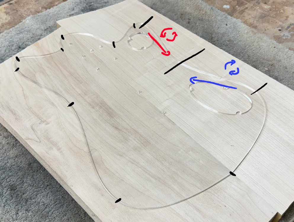
I’ve marked small black ticks around the edge of the template. If you go around the template anti-clockwise (as you would do with a hand router), and observe the grain lines, at each tick the grain goes in a different direction compared to the line I’m cutting. Now a router bit will spin in a clockwise direction (as indicated by the blue circle arrow thing), and so in the blue section where I’m “stepping down”, the cutting edge pushes the grain into the body, giving a clean cut, but in the red section, if I kept going with the same cutting tool going clockwise as before, then the router blades will lift the grain, causing tearing.
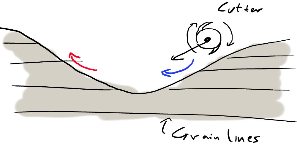
Hopefully you can see from that sketch how the blade on the router bit will lift the grains on the red cut. You can see the effect of tearing clearly here on the bass body as I progress:

This is that transition point between blue and red indicated on the annotated diagram, where I’m ramping out my blue cut and I have to go slightly into the red zone. Don’t worry, this ramp out area will be removed when I do the red pass, but it hopefully illustrates that cutting against the wood can cause quite a bit of damage.
Because I can’t change the direction the router cuts, the solution here is that for the red section I use a second router bit that has the follow bearing on the bottom, and I have to flip the workpiece over and cut from the other side, so that the red section is being cut in a grain friendly manner.
So basically to cut the body like this requires four passes: a blue and a red pass on the top half, and similarly on the bottom half. This is also why it’s important to get as much material off with the bands-aw as possible, as otherwise the excess material will foul on the shaft of the router bit I’m using for the first red pass.
It’s a lot of messing around, but on a wood as soft as poplar the tear out damage if I didn’t do this would be quite notable, as you can see. And that would then lead to sanding, and I hate sanding. Even on maple for the necks, where the tear out is much less because the wood is tougher, the little you do get is harder to work out, as the wood is much tougher :) Basically a little more time at this stage saves a lot of effort later on.
Here’s a pic towards the end when you can see I’ve just got the last pass to do:
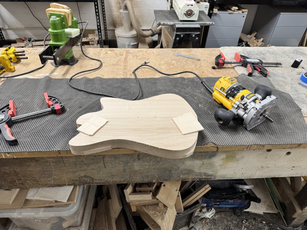
And finally the outer profile is completed!
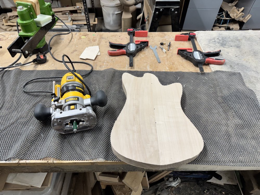
Well, I’ve done the outline :D I still have to route out the neck pocket, the control cavities, and the pickup cavities, but that’s a job for another day, as I’d also done a guitar neck at the same time (which I’ll document in the next notes), and I was getting tired, and you don’t want to mix tired and routers. It’s also hard to drink tea in all this PPE.
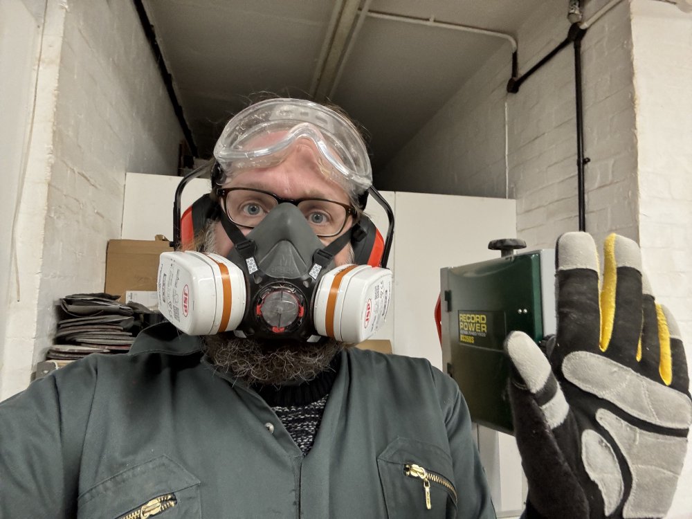
So with that I’ll sign off here, and we can talk about necks in the next set of notes!