A very brief look into OpenSCAD
Published 7 Dec 2025
I like visual CAD tooling, that is designing things by clicking and dragging and drawing on screen. A lot of what I build has a visual element to it along side any technical requirements, and so this makes sense. But once in a while I design something quite simple where most of the complexity is hidden away in the mini-spreadsheet that is the parameters form, that I might as well be doing computer programming: usually things like this are simple connectors or jigs to help me do the more interesting bits.
To take this to an extreme, there is actually a CAD tool that is based around specifying your part as a program, which is the logical extension of that parameter driven modelling. OpenSCAD is a tool based around letting you specify your model as a set of variables, as you would with parametric design in a traditional CAD program, and then using bits of code to say “make a cube with the dimensions from this parameter, and then shift it over by the amount in this other parameter, and then duplicate 3 times (where 3 comes from yet another parameter)”.
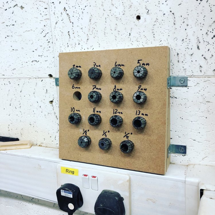
Whilst I don’t think this is ever how I’d build guitars, for certain jobs I think this would be quite a quick and simple way for me to specify the design. For example, this collet holder I made many years ago where I just need a bunch of circles increasing in size would probably have been quicker to make if I didn’t need to draw it by hand and apply the parameters to it.
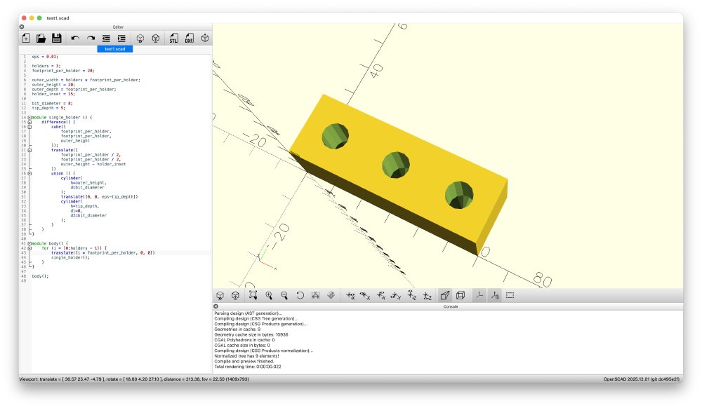
As it happens, I wanted to 3D-print myself a small thing to keep a bunch of bits in, and so I thought this was the perfect excuse to finally try out OpenSCAD (it’s what you can see me trying to make in the screenshots I’ve included).
The other thing that made me interesting in OpenSCAD is that the language itself is what’s referred to as a functional programming language, which is a style of language that I don’t get to use often for work, but is a style I enjoy programming in when I can, as it eliminates many of the opportunities for coding bugs.
But unfortunately my enthusiasm for OpenSCAD was short lived. My point here isn’t really to complain about OpenSCAD, as I admire what they’re trying to achieve, but rather just to save those who like me were curious to be a little cautious on what you can achieve with it.
The first screenshot is actually based on my final code before I gave up, but this is a more honest view of where I ended up:
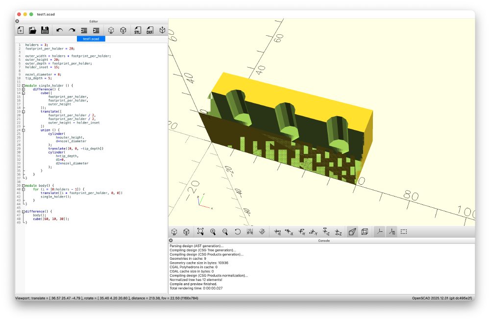
The first major program is that unlike other CAD tools I’ve used, if you put two shapes next to each other and tell OpenSCAD you want them to join or one to be used to remove parts from the other, it can’t work out what’s going on where the faces touch, you actually have to ensure that the shapes clip into each other by some small amount. No other CAD tool I’ve used before has made the user do this, and it means your design is no longer this nice mathematically pure model that you’d expect using this numbers based approach, you have to keep adding a fudge factor.
You can see in the above screenshot two issues due to lack of nudge factor: my model for a drill bit is a cylinder with a cone on it, and where the two models are joined with a union operation, although the faces touch perfectly, OpenSCAD still has a surface between them where I’d expect the union to make them into a single object. In trying to debug this I then added another cube to subtract from half the model as a hack to give me a sectional view, that cube has the same faces as the other of my model, and so you get the rest of that weird glitching you see on the bottom left in brown. this is all fixed in the first picture by adding a bunch of 0.01 mm offsets to everything to make the sectional cube slightly bigger, and have the code and the cylinder faces run past each other slightly.
This then means that my parameters can’t be just pure descriptions of how big a thing is, you need to know what it’s going to be used for so I can add or remove little fudges as I go. This crops up again if you say have a cylinder that you want to use either as a positive piece that you want to add to a design, then you specify it one way, but if you want to use it to cut a hole in another piece you have to specify it another way due to how it models cylinders internally. Ultimately, I don’t like how I have to think about all this as I’m trying to design a piece, I want the tool to work that out for me, that’s why I’m using tools, to save me effort.
I spoke with a couple of others that have tried it, and they had some other things that gave me an expectation reset also, such as the lack of filleting (rounding edges over).
I really love the idea of OpenSCAD for a certain class of problems, so I hope it continues to improve. For instance, Fusion 360, for all it’s nice parametric design, can’t handle me specifying the formula for spacing out guitar frets, which is why I have written other tools for that, but OpenSCAD in theory would make that super easy to do. I think if you wanted to explore the bounds of OpenSCAD as a hobby, then I imagine you can have a lot of fun pushing what’s possible via mathematical modelling and combining it with 3D-printing or milling, evident if you scroll down a bit on this tutorial page. But if, like me, it’s just a means to an end for specific challenges, I’d recommend sticking to other more fledged out traditional CAD tools for now.